- New Features in the Software Option Protected Areas
- Second measurement geometry in the camera feature
- Display of the workpiece origin in the camera image
- Permanent storage of variables / persisted values
- 3D Simulation: Grid can be switched on and off
- Selection fields in input dialogs of SimPL programs
- Tool check: free up space in the magazine
- Improved overview of the inputs/outputs for the configured components of the machine
- New user setting to hide the "Suction" tile
New Features in the Software Option Protected Areas
The Protected Areas option is used to protect individual areas in the machining room. Some improvements have been made to this popular option to make it easier to use.
Second measurement geometry in the camera feature
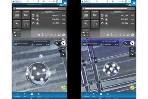
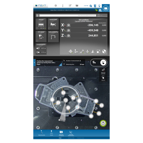
The functionality of the popular camera feature has been enhanced with version 2.10. It is now possible to draw a second measurement geometry in the camera image if the first contour is a circle or an edge. This allows you to measure a rotation of a complex component by probing two holes, two edges or one hole and one edge.
New help texts in the camera image inform you when it is possible to draw a second contour. The following combinations are permitted:
- circle, circle
- circle, edge
- edge, edge
Display of the workpiece origin in the camera image
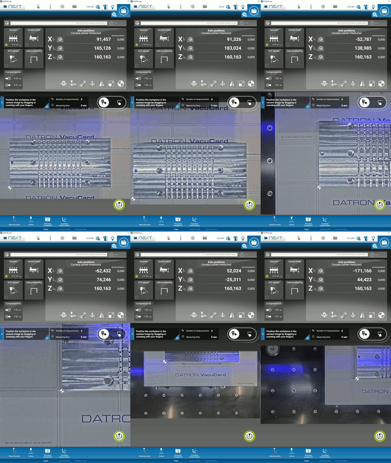
To make setting up workpieces with the DATRON next control even easier, the origin is displayed visually in the camera image.
After measuring with the 3D probe, the set origin is displayed exactly at the measured point in relation to the workpiece and will always be present in the camera image (as can be seen in the pictures). This is especially helpful if you want to adjust the position of the origin later and check whether the point is at the desired position.
Permanent storage of variables / persisted values
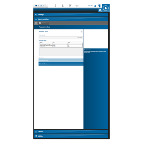
In the context of machine programming, there is often the desire to store individual data from a program for an indefinite period of time, or to read in stored data again. The stored data must survive a restart of the machine and also a software update. Typical applications are:
- Realization of counters that are cross-program or cross-execution
- Backup / restore internal states of a program
- Exchange of data between programs
For this reason, the programming language of DATRON next has been extended by new SimPL commands for creating and editing persisted values. Detailed information can be found in the programming manual under “Persisted values”. The following new SimPL commands are available:
Statement: savevalueof name
Persists the current value of the variable with the name name. You can specify global and local
Statement: loadvalueof name defaultvalue
Reads the persisted value of the variable with the name name with the data type of the variable.
Expression name hassavedvalue
An expression with the result data type boolean that can be used anywhere a value with data type boolean is allowed. This expression returns true if loadvalueof with the same name could be executed without error. This means that there is a value in the persistence for this name and with the correct data type.
Statement deletesavedvalueof name
Deletes the persisted value of the variable named name if it exists.
3D Simulation: Grid can be switched on and off
From now on it is possible to switch off the grid in the 3D simulation 🙂
Selection fields in input dialogs of SimPL programs
In a SimPL program, users can now be offered input dialogs of the type ‘Selection’. In such dialogs, the machine operator is then shown a drop-down list via which a selection can be made from any values (programmed by you).
Tool check: free up space in the magazine
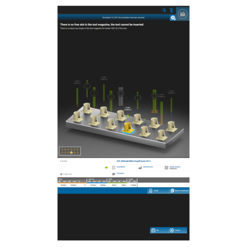
An improvement has been made in the tool check. Previously, the tool check had to be completed when a new tool had to be changed but there was no space left in the magazine. From now on, the tool check no longer has to be completed and the process runs in the following manner:
- A message is displayed that there is no more free space and that a space must be made available. At the same time, the graphic tool magazine is displayed.
- The unused tool must be marked afterwards and can be moved to the warehouse.
- After which the new tool can be used
Improved overview of the inputs/outputs for the configured components of the machine
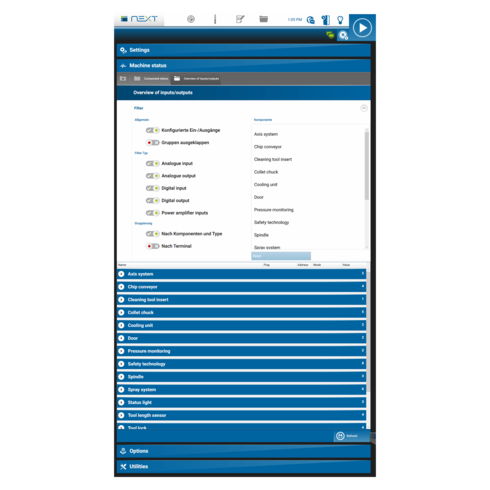
The overview of the machine components has been optically revised. This makes it easier to check the status of the respective components. The view is useful, for example, for error analysis and communication with the service department.
New user setting to hide the "Suction" tile
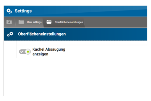
Until now the tile “Suction” was always displayed in the DATRON next – even if no suction was connected to the machine at all. In addition to switching on the suction unit, pressing the tile also deactivates the ethanol of the spray system. In order to avoid unwanted operating errors, the tile display can now be deactivated. This can be done in “Settings > User settings > Surface settings” (see screenshot).
Easier setup:
As of now, there is a simplified mode for setting up areas, in which only the most important parameters of the geometry have to be described. For a cuboid, for example, only the position and dimensions have to be entered. The number of input fields has therefore been reduced.
The other input fields known so far, for example to set the rotation of a geometry, can be found in the advanced settings.
Representation of the protected areas in the 3D view:
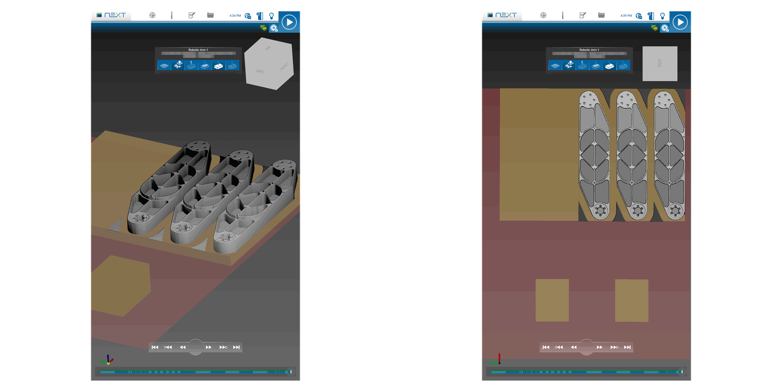
For better clarity and better estimation of possible collisions, the protected areas are now also displayed in the 3D view of the DATRON next controller. This makes it easier to judge whether the geometry has been set up with the correct parameters. A pictogram of the 3D image is also displayed in the management view of the protected areas for easier identification.
In addition to the individually protected areas, the areas that are protected by the factory are now also displayed in the 3D view. This includes, for example, the worktable and the tool changer.
Further information:
- Factory-protected areas are displayed in red.
- Individually configured protected areas are displayed in yellow.
- When setting up protected areas with the camera, the data is always displayed in extended mode, as a rotation is always measured.
- If you switch from the “Default settings” to the “Advanced settings”, the position settings are lost.
FAQ (Easier Setup):
Q: When do I use the default settings?
A: If I want to quickly set up Protected Areas manually.
Q: When do I use the Advanced Settings?
A: When I have measured with the camera (due to the measured rotation)
When setting up with a second geometry in the camera image, the rotation angle to the second geometry with respect to a certain axis is additionally displayed at the first geometry. By the way, the reference point of the rotation can easily be changed via the handle – just try it out!
