- Restart after abort
- New SimPL commands for path correction and depth correction
- New warning message in case of simultaneous activation of suction and alcohol cooling
- Parking position individually configurable
- Autocomplete function in the editor
- New optional parameters to measure rotation
- Suppression of Z measurement in the measuring cycles
- New symmetry measuring cycle (groove/bridge middle)
- Precision Rotary Axis for M10 Pro and M8Cube and MLCube
- Pneumatic Drive Unit OR Digital I/O Module 16 in/16 out
Restart after abort
If the execution of a programme has been aborted in DATRON next, starting with version 2.5 it is very easy to resume the execution at the point it was aborted. DATRON next remembers the point of the programme abortion and then offers the operator various options for comfortable resumption.
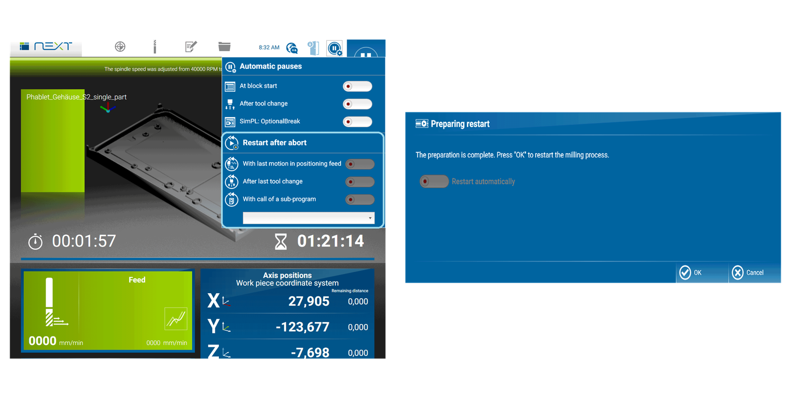
If a programme abortion has occurred, the automatic pause icon is displayed in bright orange and the menu is expanded to include the section “Restart after abort”. Below are the options you can choose from:
- With last motion in positioning in positioning feed
- After last tool change
- With call of a sub-program (that you can choose from the selection list)
To resume the suspended programme, simply press the “Start” icon at the top right of the screen after selecting the desired option.
New SimPL commands for path correction and depth correction
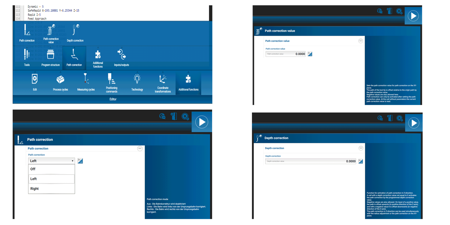
From now on there are new commands available for path correction (Pathcorrection, Pathoffset) and depth correction (ZAxisOffset) in the programming language of DATRON next (SimPL). This makes it possible to define a compensation value for the toolpath in XY and Z in the program. Goal is to make it easier to subsequently produce a certain accuracy of fit. Additional Input masks are available in the editor for easy programming of this command.
How it works:
When correction is activated, the actually executed path is offset by a programmed value relative to the programmed path to the left, right (XY axis) and upwards or downwards (Z axis). The behaviour is very similar to the tool radius compensation and similar conditions and limitations apply. These are explained in detail in the SimPL Command Reference.
- Note: Path correction on the XY plane must be activated and deactivated by programme commands within a programme, but it is implicitly deactivated at the end of a programme or when a programme is suspended.
Note: Path compensation in the XY plane in pocket and contour cycles: Unlike tool radius compensation, path correction in the XY plane can also be used for pocket and contour cycles. It has the effect that the entire pocket or contour is milled in larger or smaller size according to the correction value.
New warning message in case of simultaneous activation of suction and alcohol cooling
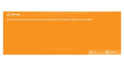
If suction is activated, alcohol must not be used as coolant because the it must not be cooled with alcohol, because the suction system is not explosion-proof. To prevent incorrect operation, a corresponding message is now displayed if alcohol is used as coolant by mistake when suction is activated.
Parking position individually configurable
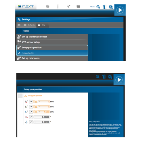
Due to multiple customer requests, as of now it is now possible to define the park position individually.
Autocomplete function in the editor
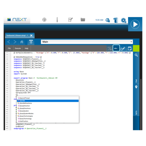
To make programming in the editor even easier, the autocomplete function is available as of now. It is activated via the abc… symbol at the upper right edge of the screen. Autocomplete suggests a dynamic selection list of available programme instructions and structure elements at keyboard input, so that they only have to be selected.
| Command | Description |
|---|---|
| PathOffset = 0.1 | Sets the path correction value on the XY plane to 0.1 mm/inch. Negative values are also allowed. |
| PathCorrection Left | Activates the path correction on the XY plane. If the correction value is positive, the system moves to the left of the programmed path. If the correction value is negative, the system moves to the right of the programmed path. |
| PathCorrection Right | Activates the path correction on the XY plane. If the correction value is positive, the system moves to the right of the programmed path. If the correction value is negative, the system moves to the left of the programmed path. |
| PathCorrection Off | Deactivates the path correction on the XY plane. |
Depth correction:
When depth correction is activated, the actually executed path is offset by a programmed value relative to the programmed path (in the direction of the Z axis). Depth correction can be used simultaneously with tool radius compensation or path correction on the XY plane.
SimPL commands for depth correction
| Command | Description |
| ZAxisOffset = 0.1 | Switches on depth correction, the correction value is 0.1 mm or inch. Negative values are also allowed. If a positive value is entered, the path is moved upwards (in the positive direction of the Z axis) and downwards (in the negative direction of the Z axis). |
- Attention: When depth compensation is activated tool changes and measuring cycles cannot be executed.
- Note: Depth correction must be switched on and off by program commands within a program, but it is implicitly switched off at the end of a program or in the event of a termination.
- Note: Depth correction can also be used in pocket and contour cycles. It then has the effect that the depth of the entire pocket or contour is corrected by the compensation value.
Innovations in the measuring cycles
New optional parameters to measure rotation
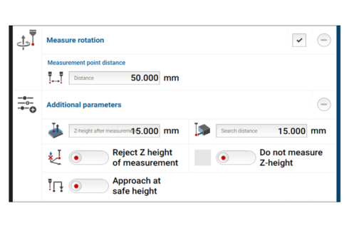
As of now it is possible to measure the rotation of unmachined parts via further, optional parameters, in all measuring cycles (without camera) of the DATRON next control, in case a component is not lying parallel to the axes on the table.
Note: In the “Circle centre point” measuring cycle, the parameters for rotation measuring allow to measure the rotation of a blank by probing two holes in any position. HSCpro users know this function from the “two-hole rotation macro”

Suppression of Z measurement in the measuring cycles
The Z measurement can be completely suppressed, or the measurement result can be rejected in every measurement cycle if the previous result is to be used.
New symmetry measuring cycle (groove/bridge middle)
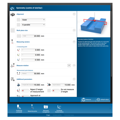
There is a new additional measuring cycle available for the determination of the symmetry axis of a workpiece. This is useful, for example, to determine the centre between two vice jaws.
Note: For further details on the new features in the measuring cycles, please refer to the DATRON next manual (Version 2.5).
Support of optional DATRON accessories
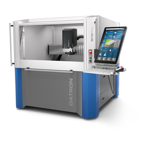
Precision Rotary Axis for M10 Pro and M8Cube and MLCube
DATRON next, starting with version 2.5 supports the precision rotary axis (not for DATRON neo – for this a separate rotary axis is available). It is implemented as A-axis, which means that installation always has to be parallel to the X-axis.
Pneumatic Drive Unit OR Digital I/O Module 16 in/16 out
DATRON next, starting with version 2.5, supports the pneumatic control unit and the use of the digital I/O module.
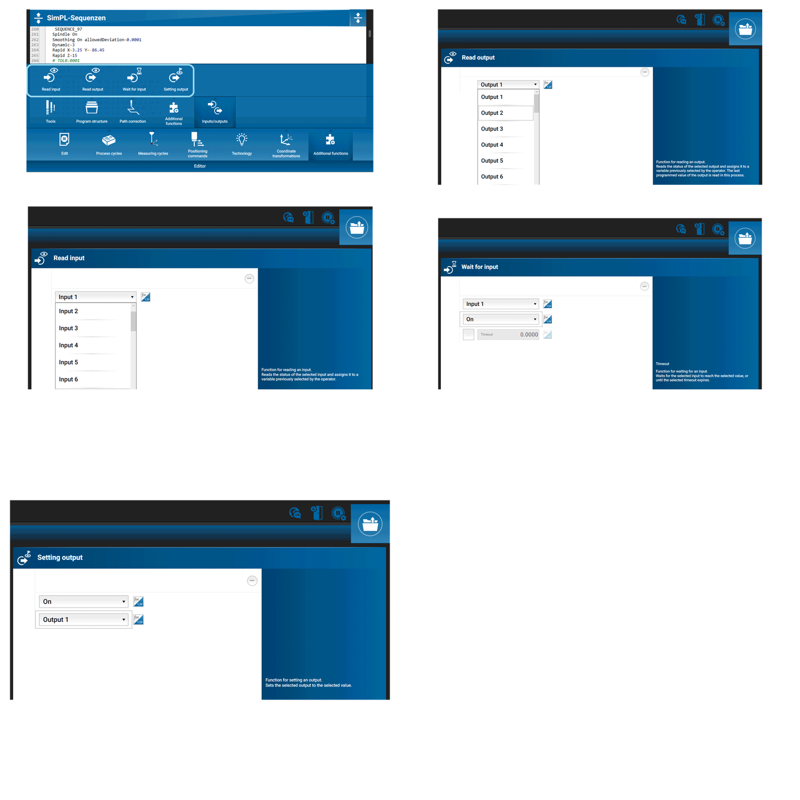
The editor of next contains the following associated programming commands:
- Read input
- Read output
- Waiting for input
- Set output
