
- From now on the rotary swivel table can also be used with DATRON next
- Individual influencing of the tool management or sister tool options by means of SimPl commands
- Simple document management for viewing and managing DATRON programming manuals / operating instructions
- User tool catalog easily transferable to other DATRON next machines
- Improved workpiece simulation for all tool types
- Measuring cycles for measuring tilting or twisting of a workpiece using several measured Z-heights
- Polish can now also be set as a language option in DATRON next
- Speed reduction when moving the axes in manual mode
- Tool breakage control without setting the tool length again
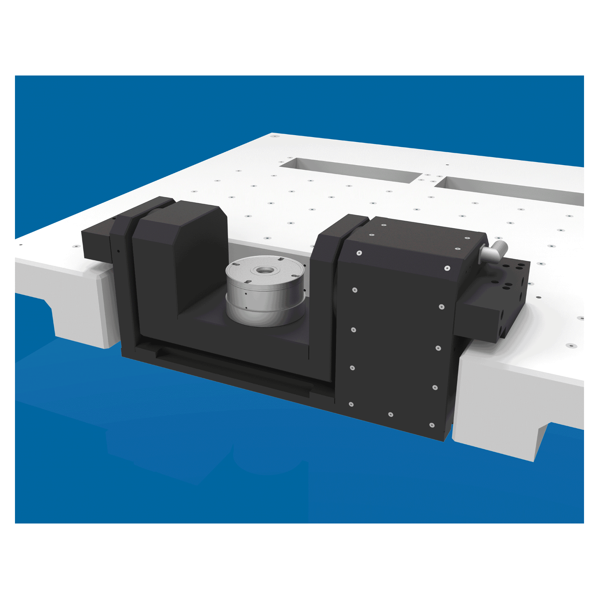
From now on the rotary swivel table can also be used with DATRON next
The installation of the rotary swivel table or rotary axis in a DATRON next machine is always carried out by a service employee. After installation, two small steps are required before commissioning.
- you need at least the 2.12 version of the DATRON next control.
- the rotary table must be activated by a service employee in the component configuration in DATRON next. (Figure 1.1)
Then the axes of the rotary swivel table or the rotary axis can be calibrated independently after each disassembly and assembly. This has the advantage of avoiding inaccuracies when the rotary object or the rotary and tilt table is reused, thus maintaining the milling result at the usual high level.
For independent calibration there is a setup dialog in DATRON next. You can find this under “Manual operation” under “Service”. If you have clicked the button “Calibrate rotary/swivel table” (Figure 1.2) there, you can follow the setup dialog step by step. (Picture 2 and 3)
Individual influencing of the tool management or sister tool options by means of SimPl commands
Starting with the 2.12 version you can now set the values of your tools yourself. Whereas in the previous DATRON next versions you could only read out the values of tools (GET commands), it is now possible to actively change the values of tools using the new SET commands.
Changeable values of tools:
- Maximum tool life
- Maximum service life
- Current standing distance
- Current service life
- Locking a specific tool (since 2.11)

Simple document management for viewing and managing DATRON programming manuals / operating instructions
Document management is a completely new option integrated in DATRON next. It enables you to open and search all kinds of manuals and operating instructions quickly, offline and locally. You can obtain the manuals free of charge from the service department and create them in your DATRON next. This means that you do not always need an Internet connection when you need help with machine operation.
Step by step instructions:
- First of all, you can request the desired documents via the service. These could be DATRON programming manuals or DATRON next manuals, for example.
- These documents are available in PDF format.
- Then you can load the documents onto a USB stick and plug them into a USB port on your machine.
- The machine will automatically recognize the documents on the USB stick
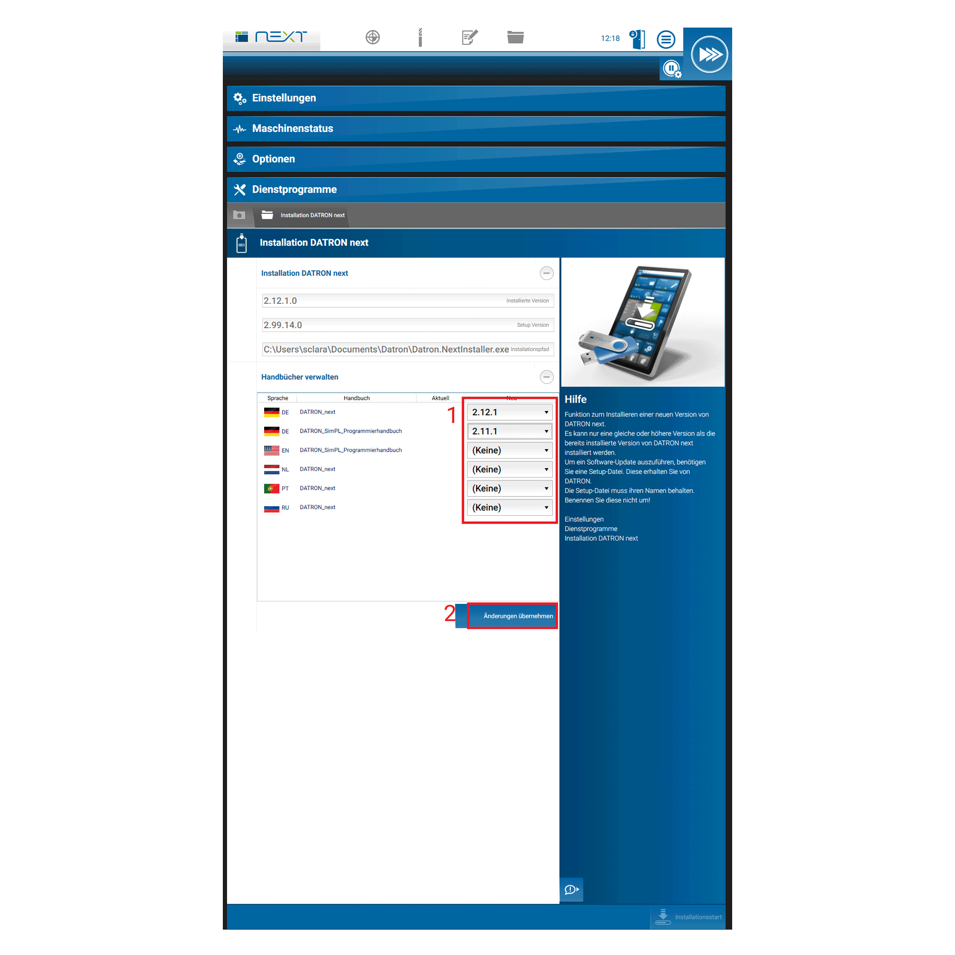
- You can activate the documents on your DATRON next machine under “Settings” –> “Utilities” –> Installation DATRON next
- Each document can be activated or uninstalled individually
The DocumentViewer program can be found on the DATRON next start page in the upper right corner (see Figure 3)
After you click on the button, the program opens. Here you can also quickly search for terms with CTRL + F. (Picture 4)
User tool catalog easily transferable to other DATRON next machines
User tool catalog easily transferable to other DATRON next machines
To save you the time of manually entering your user-defined tools on several DATRON machines, there is now a new tool catalog import and export function. Besides the time advantage, you can now maintain your user tool catalogs on your PC or import them into CAM programs.
Step by step guide:
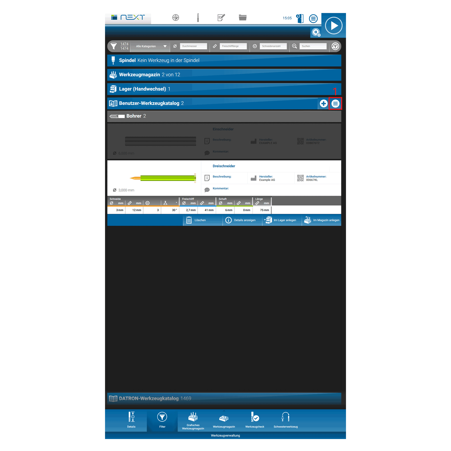
- First you navigate from the main menu to your user tool catalog via the tool management
- When you click on “User Tool Catalog”, two options appear on the right side of the blue field. The right button is for the import-export function (Figure 1)
- If you click on the right button, you can choose between import and export, or view your catalogue (picture 2)
- If you select import, all available USB sticks or server systems from which you can import catalogs to your DATRON machine are displayed. You select a location by clicking on “Select path” at the bottom right (Figure 3)
- If you select export, all available USB sticks or server systems on which you can save catalogs of your DATRON machine will be displayed. You select a location by clicking on “Select path” at the bottom right (Fig. 3) when exporting, you are also given the option of renaming tools and catalogs. (Picture 4)
Improved workpiece simulation for all tool types
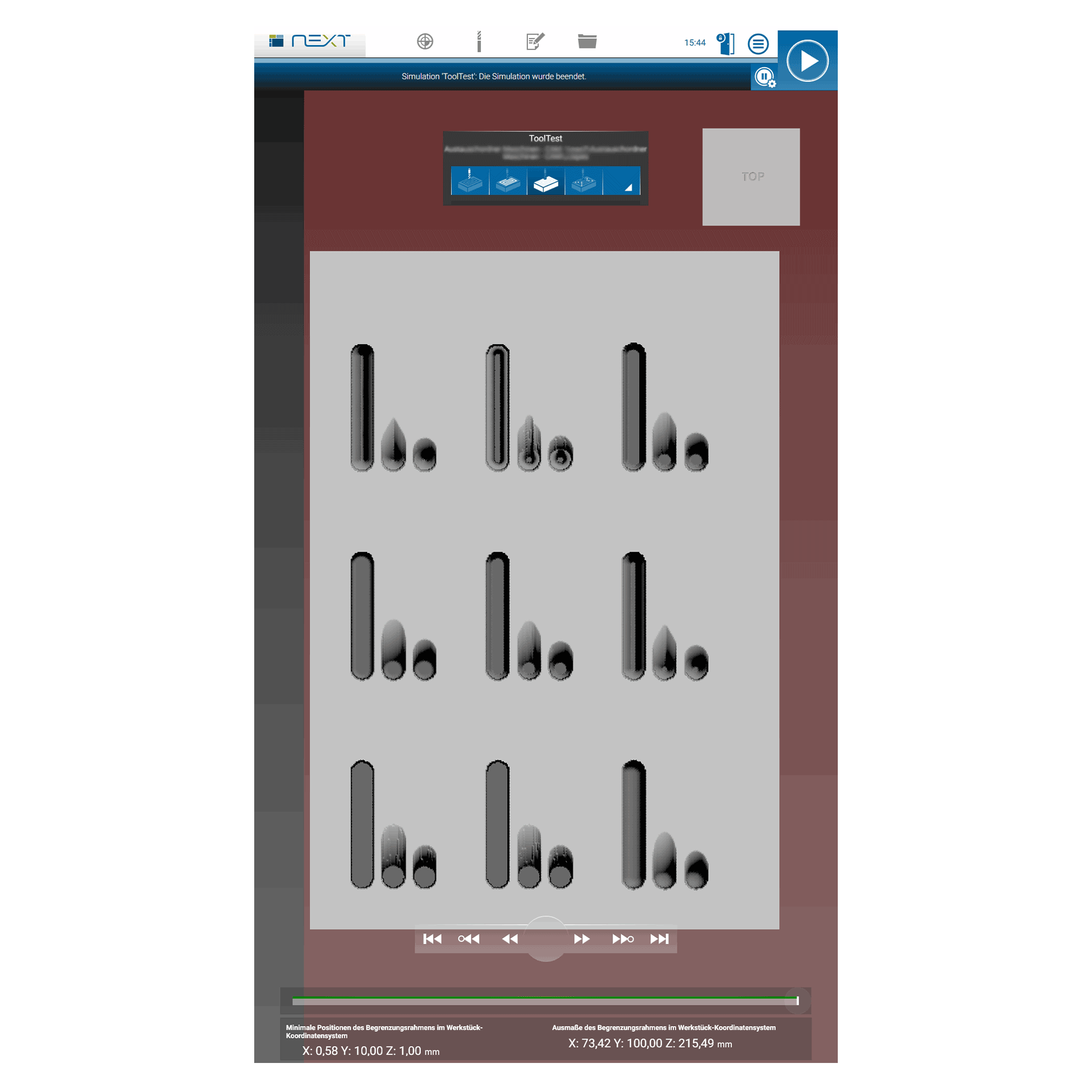
With the improved simulation of workpieces in DATRON next, you can now better understand how the workpiece looks before you have milled it. This also gives you better control over how your workpiece is programmed.
The improvement affects the following tool types (see also pictures):
- Drill
- Couter Sink Miller
- Engraver
- Face Miller/ plain milling cutter
- Ballnose Miller
Examples of improved simulation:
Removals of the above tools are now displayed in the part
Holes with drilling tools that were previously not visible in the simulation are now displayed
Engravings and fine ablations with different engraving gravers are now simulated more accurately
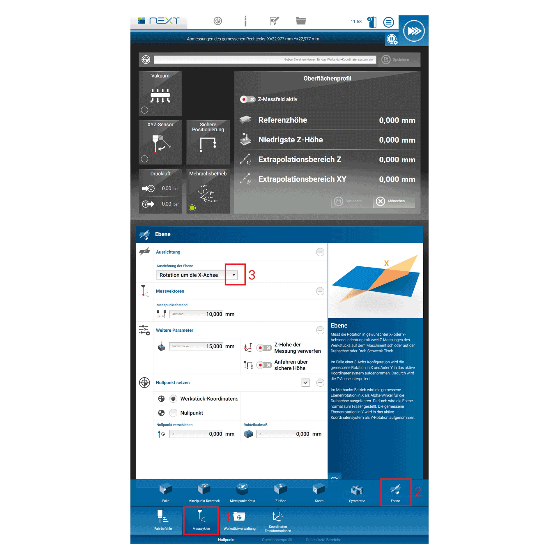
Measuring cycles for measuring tilting or twisting of a workpiece using several measured Z-heights
These are three measuring cycles with which the orientation of the X-axis (Fig. 1), Y-axis (Fig. 2) or X-Y plane (Fig. 3) can be determined. When working with rotary axes, this helps to rotate a workpiece into the correct position or, when working with 3-axis kinematics, to interpolate the plane.
The software option “surface profile” or an activated rotary tilt table are prerequisites for using this function.
In addition, this new function also helps if inaccurate milling results are obtained, for example because the workpiece was clamped incorrectly. In such cases, tilting or rotation can be measured. When milling, this is taken into account and accurate milling can be carried out despite tilting.
The measurement can be carried out in X or Y direction on the machine table, the rotary axis or the rotary/swivel table. (see pictures 1-3)
Polish can now also be set as a language option in DATRON next
The next control is now also available in Polish. You can select the language by clicking on the round menu button in the top right corner of the main menu and then selecting the lower button with globe and speech bubble. (see also picture)

Speed reduction when moving the axes in manual mode
Um Kollisionen im Handverfahren am Bedienpult zu vermeiden, wurde die Geschwindigkeit der X, Y und Z Achsen verlangsamt. Das betrifft ausschließlich das Verfahren im Handbetrieb. Die Geschwindigkeitsreduzierung gilt nicht bei Fahrbefehlen mit der DATRON next Steuerung und auch nicht für Eilgang oder Vorschub Geschwindigkeiten.
- Geschwindigkeitsreduzierung der Z Achse auf maximal 5m/min bei allen Maschinen
- Geschwindigkeitsreduzierung der XY Achsen auf maximal 20m/min bei allen Maschinen
Handbetrieb bedeutet das Verfahren der Spindel mit dem Bedienpult, während kein Programm geladen ist. Hierbei ist auch das Einzelschrittverfahren am Bedienpult ausgenommen. (siehe auch beigefügtes Bild)

Tool breakage control without setting the tool length again
Previously, if a breakage was detected during a tool length measurement, the new length of the tool was saved and a warning message was always displayed to you as the operator.
With the new extended function (since v2.12), a tool length measurement can be arranged from SimPl in the program without overwriting the value of the existing tool length afterwards.
This is interesting for you as a customer, if you want to mill with a shorter tool and the machine should not be informed about it
- Normal case: MeasureToolLength
- New orders: MeasureToolLength skipSaving, MeasureToolLength skipSaving=true
All internal, automatically triggered tool length measurements continue to represent the “normal case”. For example, length measurement before depositing or after picking up a tool. Whether these automatic tool length measurements should be carried out can be defined in the user settings.

Application cases Example
- If you know from your CAM program that your tool has, in some cases, a higher wear than normal, you can overwrite the current or maximum tool life or tool path with your own CAM values
- You can also specify exactly where in the program the overwriting is to take place
- You can also check the tool life of a tool during a program, if the length of the path to be covered by your program is already known beforehand and then set a maximum tool life by means of SET commands, or overwrite the current tool life
| SetToolLifeMax | Setzt die maximale Standzeit des Werkzeugs auf den angegebenen Wert. |
| SetToolLifeTotal | Setzt die aktuelle Standzeit des Werkzeugs auf den angegebenen Wert. |
| SetToolPathMax | Setzt den maximalen Standweg des Werkzeugs auf den angegebenen Wert. |
| SetToolPathTotal | Setzt den aktuellen Standweg des Werkzeugs auf den angegebenen Wert. |
| SetToolIsLocked | Funktion zum Sperren oder Entsperren eines bestimmten Werkzeugs. |
New features are also described in more detail in the 2.12 DATRON programming manual. This can be obtained free of charge from DATRON service staff.

